A new year and many projects on the horizon. Before I start anything new, my top priority is getting the miniature jack planes done and sent away. As I gather the pictures for the next jack plane post, I decided to share this on my melting furnace. I wrote this post a year ago and never posted it because I wanted to see how the furnace would hold up over multiple melts. Some changes have been made to the furnace, I will talk about those at the end.
This is for entertainment purposes only. You have to understand the risks of such a project, electricity is no joke. I am in no way responsible for any fault that may occur in trying to create what I have done.
I decided to set up a lost wax investment casting system in my basement shop. It was the next step towards achieving small production with my miniature work . The setup consists of a vacuum investment machine, a kiln to burnout the wax patterns, and a way to melt the metal. In college jewelry classes we always used a torch (oxy & acetylene or propane) to melt our metal. In my crowded basement shop I wanted to avoid having compressed gas cylinders, at the same time I wanted to melt more than a couple ounces at a time, which is doable with a torch but not very efficient. In the fall I had the wonderful opportunity to stay with miniature maker Paul Hamler for a few days. He uses the investment casting process in a lot of his miniature work. This is where I first saw and used an electric melting furnace. It had a 2.2 pound capacity crucible and a digital display. The metal is loaded in the crucible, temperature is set slightly above melting point, and a 15 minute wait until it is ready to pour. On 110volt!? It seemed to easy to be real. Bottom line... I needed a electric melting furnace for my setup. They are commercially available, but pricey and cheaply made. They are available for $400-$1200 ranging in quality. I know it could pay for itself with one pour, but I could not bring myself to buy an expensive cheapo.
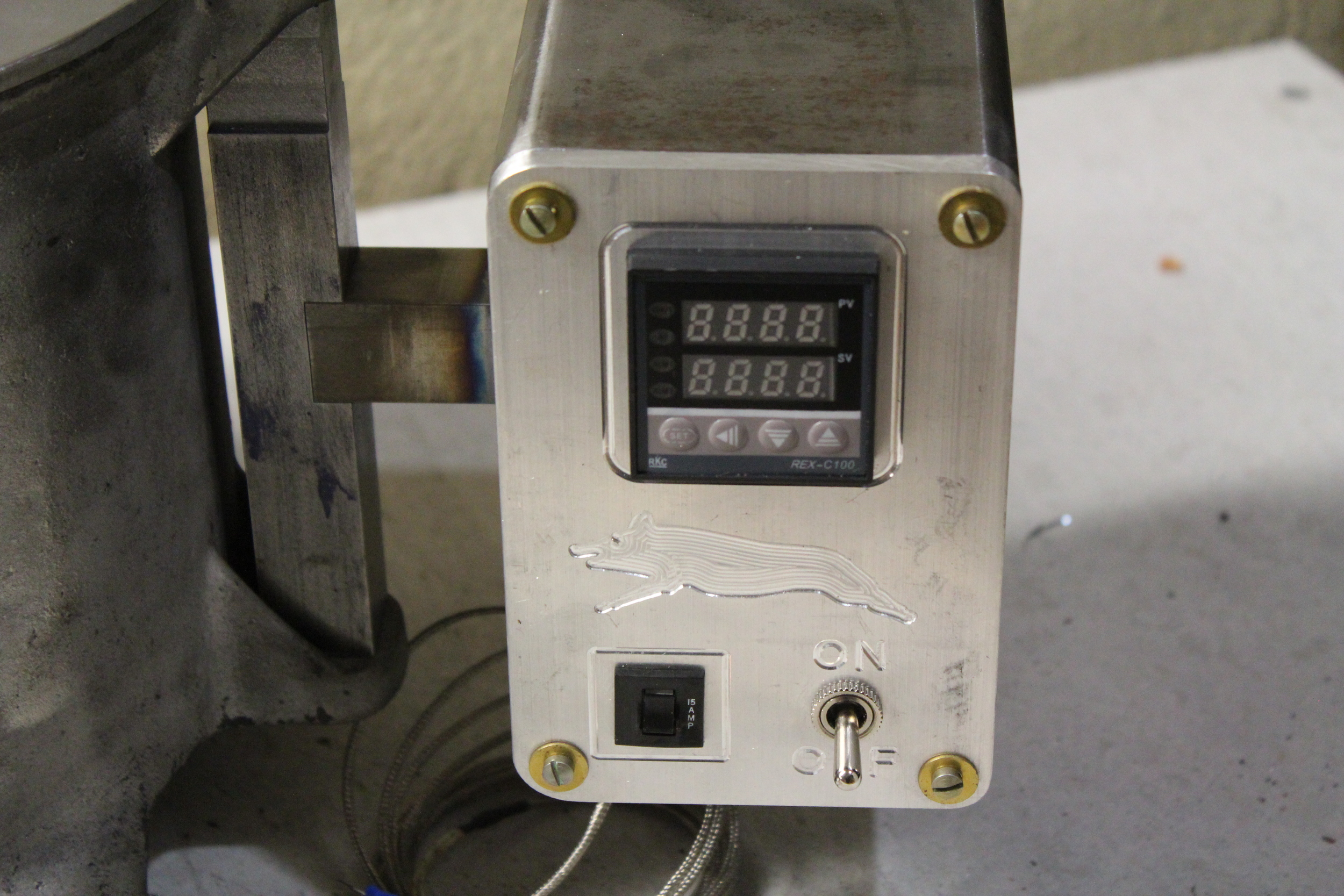
Electric furnace guts are just like a ceramics kilns, except the heated chamber is very small. Slightly larger than the crucible that fits it. A Ni-chrome resistance wire is the heating element. A PID digital temperature controller uses a k type thermocouple to sense the temperature in the chamber, telling the solid state relay (SSR) when to turn the power to the element on and off. The heated chamber is kept extremely insulated using 2 inches of ceramic refractory blanket.
I originally planed on fabricating a housing for the whole furnace. I thought about using a salvaged Freon or propane tank modified with feet, and a hinged lid. For the hell of it I went on eBay and searched"cast iron pot". I came across an antique sausage stuffer base. 6 quart size. As soon as I saw it, I could picture myself lifting a glowing crucible out of it. I checked the measurements of my components... it was too good to be true, and only $35. It was a single part as well. I hate to dismantle a complete antique to use one part.
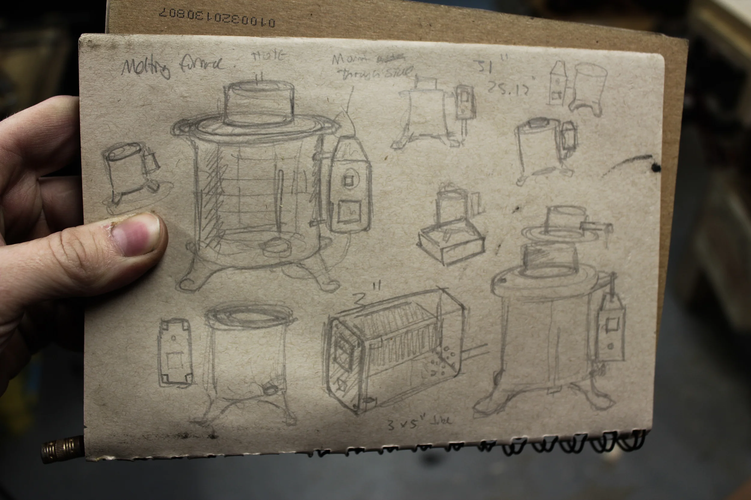
Furnace configuration sketches
Once I received the eBay goods, I did various sketches to figure out how I was going to fabricate and mount the electronics box. I dug through the scrap bin and found a piece of structural rectangle tubing the perfect size to hold the electronics. I also cut 2 pieces of 1/4" aluminum plate to cap off each end. I used heavy duty plate and tubing for no reason other than I like the weight, and dislike the sound of thin sheet.

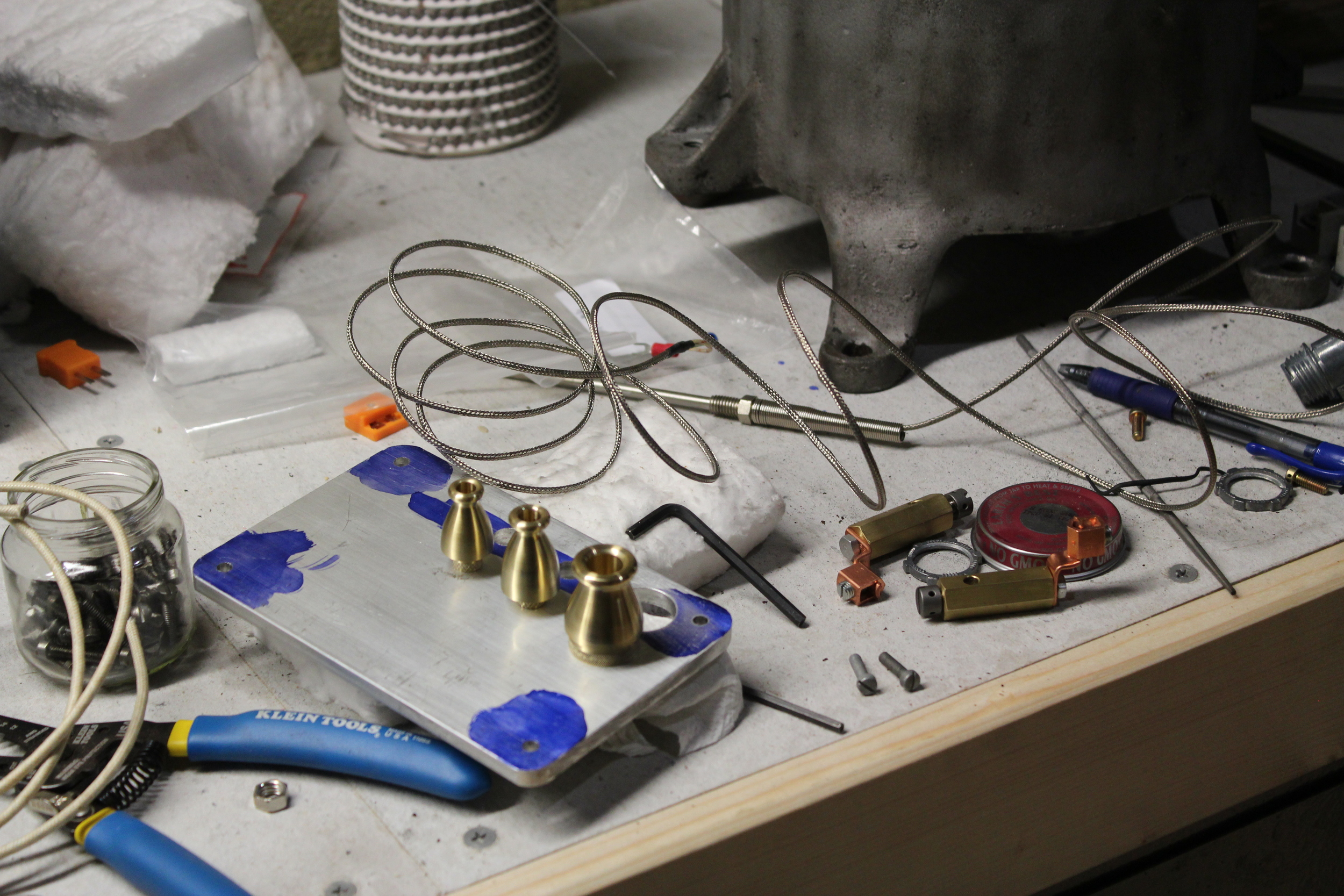
This is just about all the components I purchased to build the furnace (minus the power cord, refractory blanket, and high temp leed wire) I bought the cast ceramic chamber and Ni-chrome element on eBay. It is sold as a replacement part for commercial melting furnaces. I opted for this because the element is already wound and cut to length to wrap the chamber. Also, it is the right gauge wire to heat using 110v. That combo also came with a ceramic flange to hold a 1kg graphite crucible. The two 1-kg capacity graphite crucibles were also purchased on eBay from the same seller. The PID controller, thermocouple, SSR, and heat sink were also bought on eBay from a seller that compiles them into a "kit" for building a kiln. Some money could be saved buying the components separate, but it was nice to get them all together knowing they were right for each other. The brass connectors sitting up front are used to connect the high temperature lead wires to the Ni-Chrome element. I made these because I had the stock and enjoy brass turning, but they could be purchased from a kiln parts supplier.
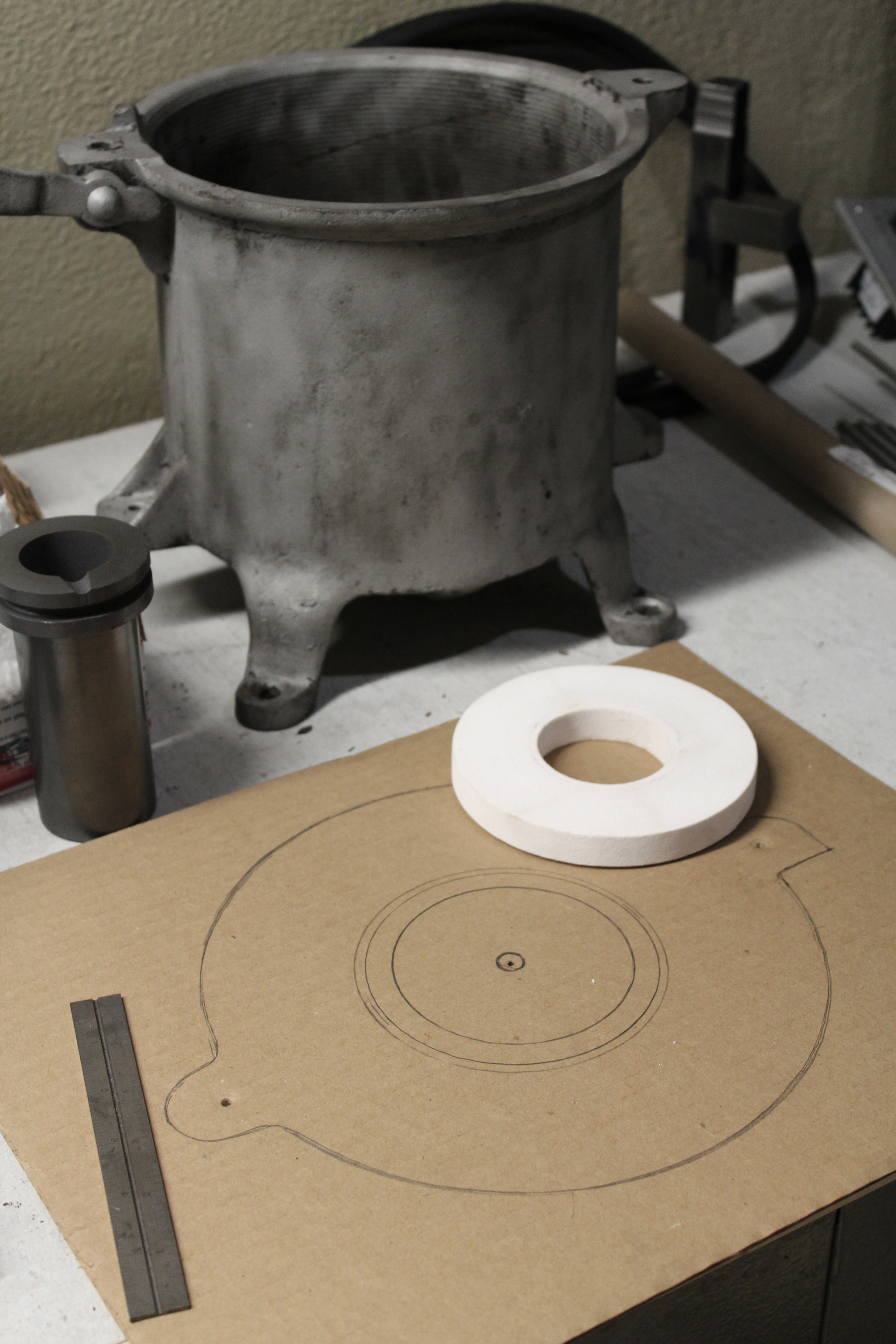
Step one was sandblasting the antique sausage residue off of my new cast iron pot. A cardboard template was made to cover the chamber and insulation. It also gives the ceramic flange a place to rest. This template would later be transferred to 3/16" plate steel.

Since the top of the sausage stuffer casting was not flat, and I needed to bolt a flat plate onto it, I bolted it down to the Bridgeport mill and flattened the whole top. The mill made quick work of the cast iron. The bottom tabs on the casting made the milling setup easy, and solid.

The thermocouple probe has a threaded collar to mount it. The location of the hole to drill and tap in the casting to accept it is determined by the hole in the ceramic chamber I bought. I centered the chamber in the pot and determined where to drill and tap. Turns out it was on a bad spot on the casting... right on the edge of the downspout underneath. I used a 3/4" end mill on the Bridgeport to scoop out enough clearance to thread in the thermocouple.

Milling the clearance for the thromocouple

cover template transferred
Here is the top flange before cutting it out. It is 3/16" steel plate. This flange keeps all the ceramic insulation packed in, as well as hold the ceramic flange for the graphite crucible. I had to cut it out the dirty way... with a 4-1/2" cut off wheel. I prefer those super thin Diablo wheels available at home depot. Being thin, they remove less material and cut a tighter radius. They also last longer than you would think. I have tried countless wheels from every welding shop, and I still prefer the thin depot wheels. Unfortunately I do not have pictures of roughing out the flange, but it was a dusty mess.
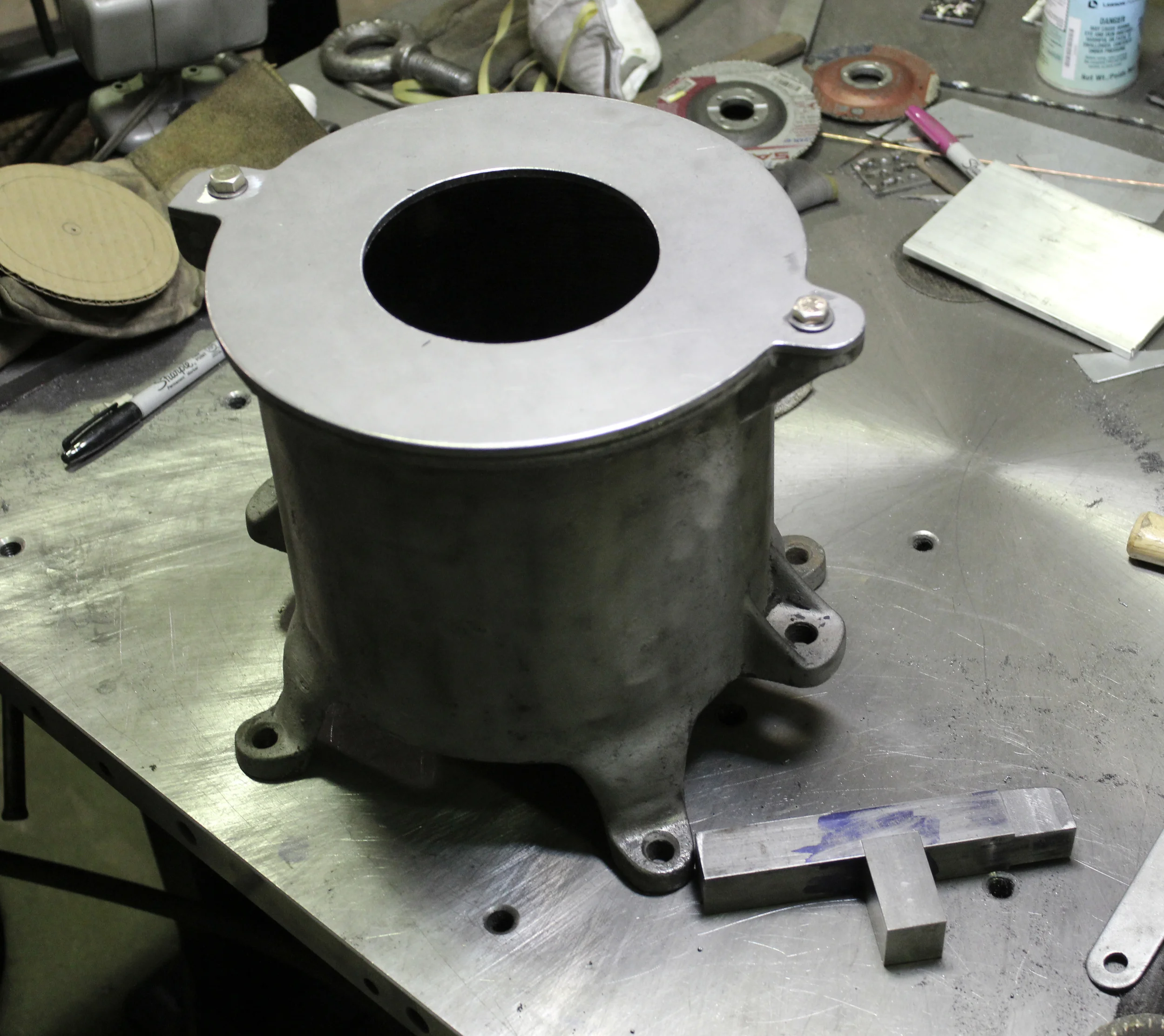
Once I had the flange roughed out and the mounting holes drilled, I bolted it to the pot casting temporarily. Staring with a grinding wheel followed by files and finished with a sanding flap disc, I shaped the outside of the flange flush with the casting. The pieces of square stock laying on the table in the picture is the mount for the electronics box. It is two pieces of 1" sq. steel stock. I decided to mill out a joint at the T just because I wanted to spend a little more time on the Bridgeport mill. I could have welded them and saved some time, but that is no fun.
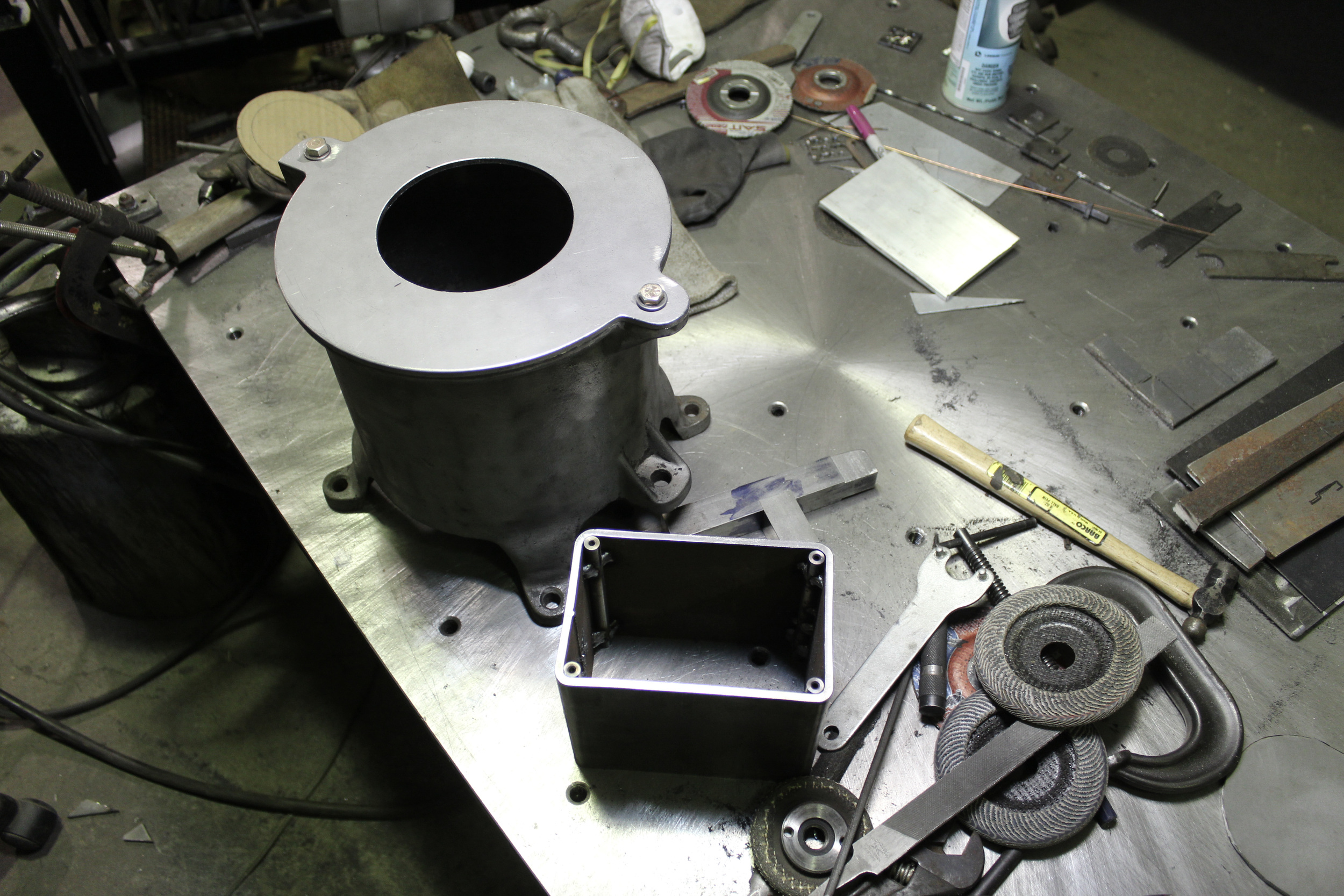
Here you can see the electronics box in the rough. Since I wanted to bolt the face plate and back plate on it, I had to add threaded pieces of stock to each corner. I could have tapped into the wall of the tubing, but it would of been very small. I used lengths of 1/4" solid round, cut and faced them to length, then drilled and tapped each end on the lathe. I then tack welded the rods in the four corners of the box

The panel to mount the electronics on started as a simple idea that quickly escalated into a project in itself. It seems that is how everything is. The only aluminum I had that would cover both the front and back was 1/4" thick, slightly thicker than I wanted. I wanted to try cutting aluminum with my small CNC Sherline mill. I have only used the cnc for wood and wax in the past, this was the perfect project to try some metal. The Sherline being a small bench top machine, only likes light cuts in aluminum, so it took awhile. I neglected to take any photos of the plate being cut out. I put a flying pig on there to pay homage to the sausage stuffer.

Dry fit of the major components.
Another unintentional side track within a project. I drilled big holes in the back of the electronics panel because I was going to use commercially available conduit connectors to hold the wires. Turns out, after I drilled the holes in the plate, the connectors did not have enough tread to go through the thick aluminum I used. So I turned brass grommets that fit into the existing holes I drilled. I love turning brass and used this as a opportunity to make them fancy. I knurled the end and press fit them into the aluminum plate after I painted it. Although hardly seen in the final piece, they were worth it.
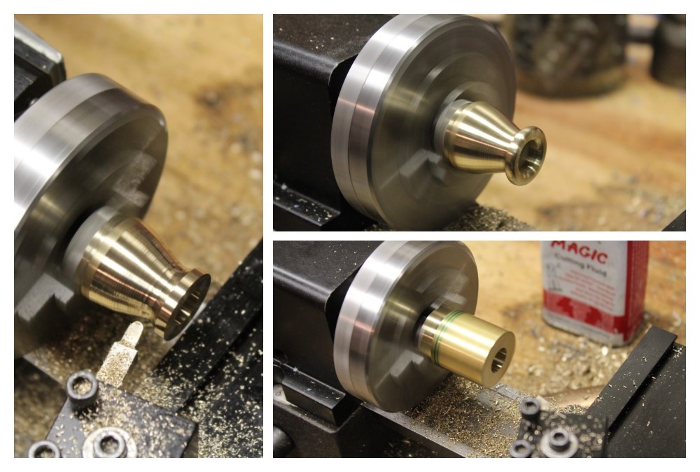
Stages of the brass grommets
Finished grommets.

Detail of the control box mount
I am not going cover exactly how it is wired. I used crimp connectors and heat shrink tubing to keep it clean inside the control box. Power comes into the box, and though a toggle switch and circuit breaker. It is then sent to the temp control and relay. The relay has a heat sink because it generates heat switching on and off. I put thermal compound between the relay and heat sink. I then cut a cross vent in the bottom of the control box and mounted the heat sink in there.
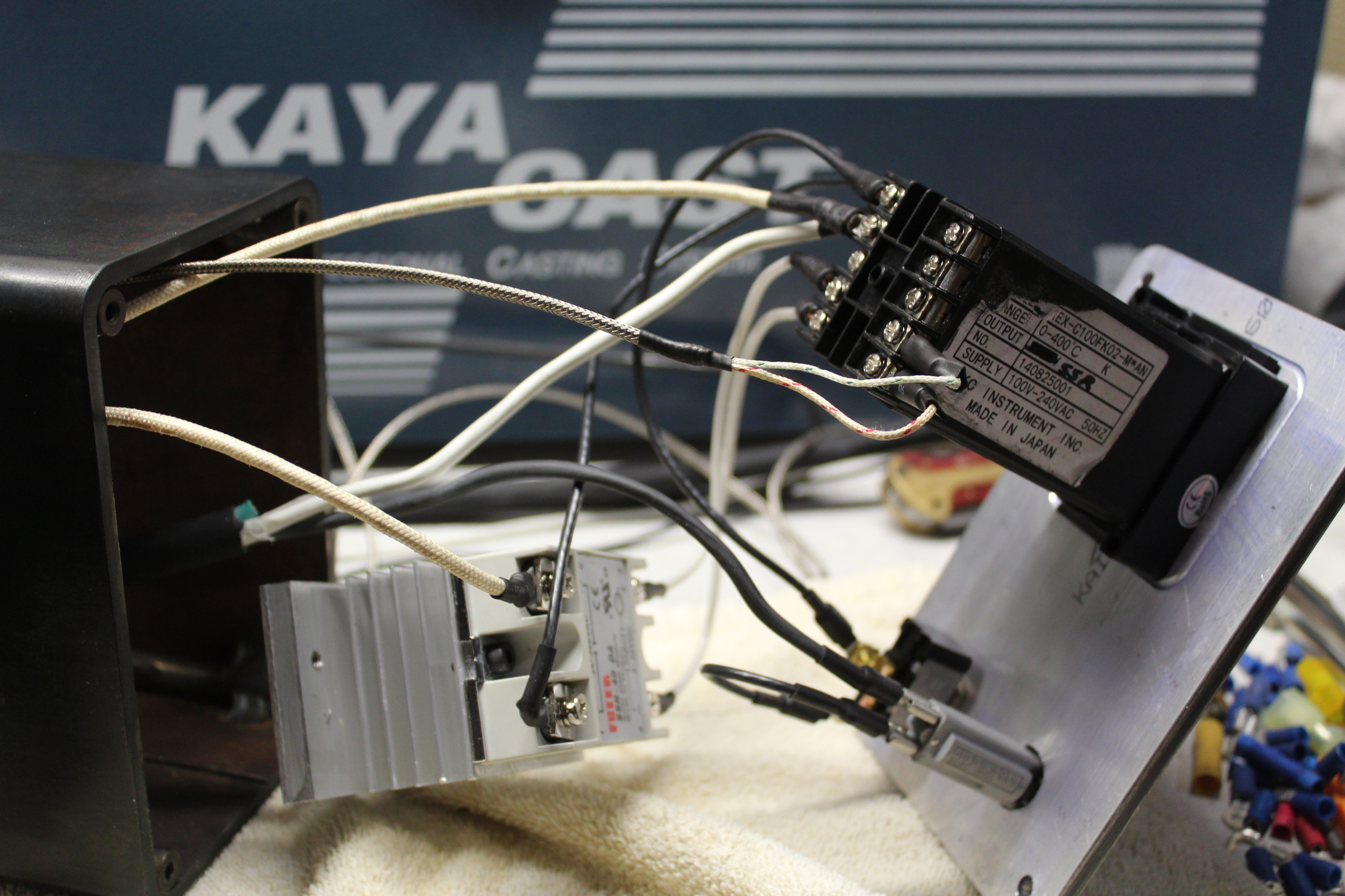
Nest of wires
As I previously stated, the heating element I purchased was already coiled and cut to length to fit the ceramic chamber. It is extremely springy before it is heated up, so winding it around the chamber took some wrestling around. Once fired for the first time, the wire eases up and holds in its position.

I determined where the wire leads had to poke out of the housing and drilled holes for them. I carved two firebrick grommets to keep the wires from touching the cast iron. If they did touch the iron it would short out everything because it is a resistance wire. Before I fit the chamber inside the cast iron housing, I put a one inch layer of refractory ceramic wool (kaowool) on the bottom of the pot. I than placed the wrapped chamber inside making sure the thermocouple was in the right spot. I than proceeded to stuff high temp ceramic wool insulation around the chamber.


After a handful of melts, I burned up a coil and decided to change this. I determined the element was to tight within the wool and it over heated because the element was getting much hotter than the probe knew about. There are a number of other reasons it could have burned up, I will never know for sure. I rebuilt it with wool around the edges leaving a quarter inch gap between the insulation and heating element. So far so good on this setup.
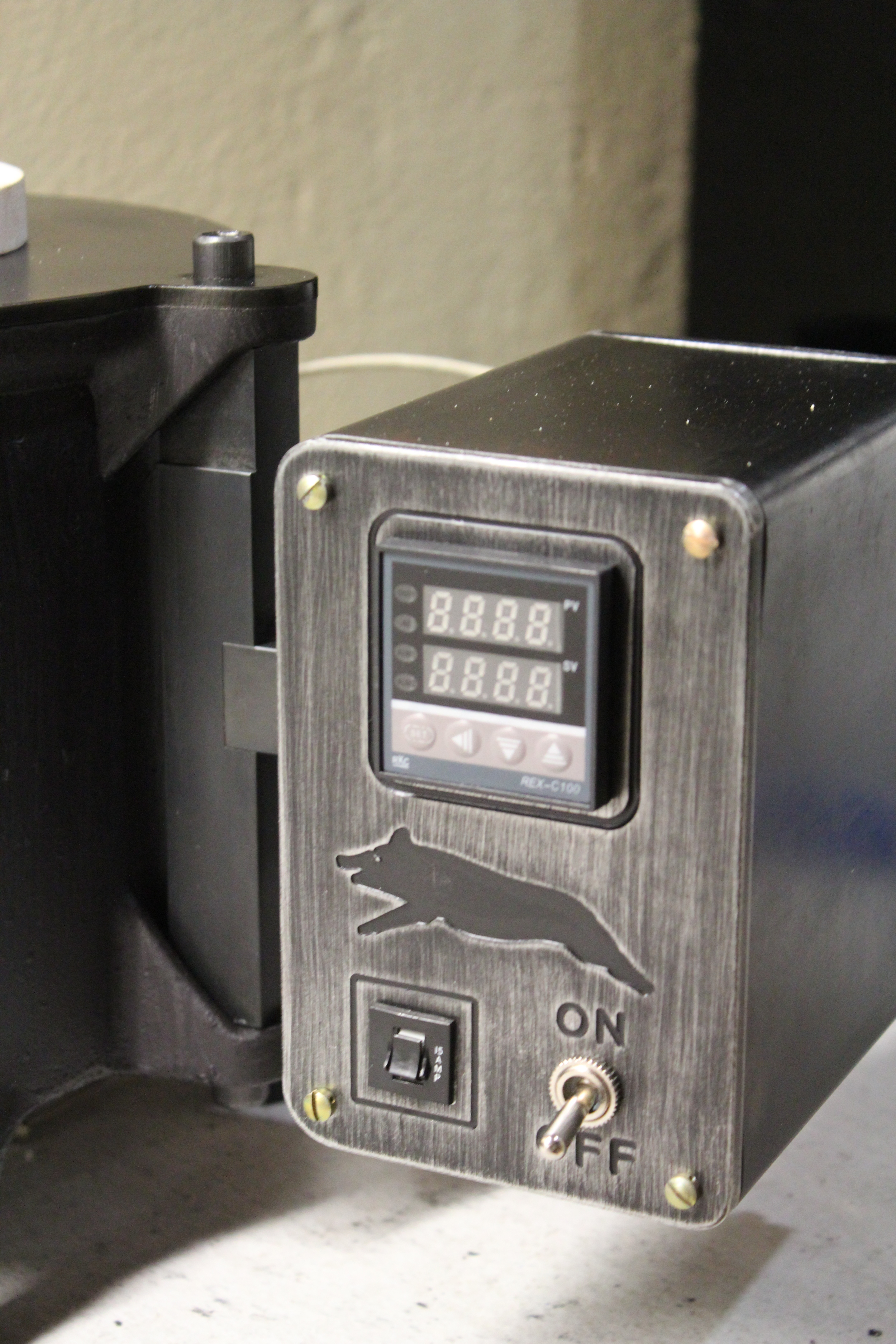
Finished.
I painted the cast iron with high temp barbecue paint. The control box and connector I chemical blued and waxed. The control panel is a black spray paint wash. The part not pictured here is a firebrick lid to cover the heating crucible. I also am thinking about making a cover for the live wires in the back.
The furnace has held up for a number of pours. It works very well. I usually set my melting temp and let it heat up for 20 minutes before adding the metal. This insures the top of the crucible is hot at the spout. I then add my preheated metal chunks and wait about 10-15 minutes for them to melt. I still get nervous using it, just because its homemade and electric. I keep torches on standby in case anything fails.
Some final pictures...

Finished Melting furnace


One of the first things I poured was this bronze name plaque. I have been dreaming of making a plaque like this for sometime. It felt surreal knowing it was made start to finish in my basement shop. I CNC cut the wax pattern for it on my Sherline mill. I left the two areas under the text for stamping numbers if this were to be attached to a larger piece of work. I am not set on this design, it was just a test piece. I plan on making a miniature version of this plaque to attach to the wood boxes of future projects.
